Reference Bearing
Description
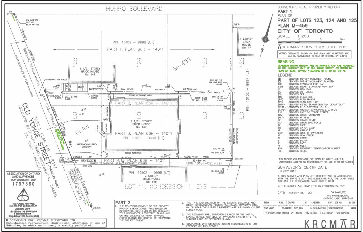
Bearing information for all boundaries shown on the plan is related to the reference bearing. This is shown on a note below the title block that identifies the orientation (direction) from which all other property line bearings on the plan are related. It is also noted on the plan itself and defined by physical survey monuments. Usually these are along the road. North is the direction used for angular orientation of all boundary limits on a survey plan. The angles measured east of the north arrow are shown as NORTH 72“ 32“ 20“ EAST. The angles measured west of the north arrow are shown as NORTH 38“ 21“ 00“ WEST. South-east and south-west identifiers are not used in any bearing/direction on the plan as Ontario land surveyor practice converts these to north-west and north-east respectively. How is the north direction actually measured by surveyors? In the early days, using the North Star as the reference point for observations, land surveyors used a theodolite to measure azimuths (astronomic bearings). Nowadays, surveyors use GPS technology and a network of existing “ horizontal control monuments (HCM)“ to determine azimuths and bearings on their survey plans.
Purpose
The note identifies the orientation of the primary root bearing (direction) from which all other property line bearings on the plan are related to. The reference bearing as defined by physical survey monuments and/or real world coordinates, puts that primary root bearing on the ground.
Why is this important?
Source bearings identified in bearing note sometimes differ between adjacent surveys resulting in possible confusion and conflict over boundary locations. This can result in two surveys depicting the same line with different bearings. The surveys are not incorrect. They still describe the same physical line on the ground; only the bearings have been rotated.
Protect Your Boundaries Inc. is a licensed member of the Association of Ontario Land Surveyors, and is entitled to provide cadastral surveying services to the public of the Province of Ontario in accordance with the provisions of the Surveyors Act R.S.O. 1990, Chapter S29.